To properly implement secure design principles in network architectures, it is important to fully understand all of the technologies involved in computer communications. From software and hardware to encryption and beyond, there are many standards to know and procedures to follow. The OSI model has become a common reference against which all protocols can be compared.
The actual OSI protocol was developed to establish a common communication structure for all computer systems but was never widely adopted. Instead, the theory behind the protocol serves nowadays as a theoretical model for how protocols should function in an ideal world on ideal hardware.
The Open Systems Interconnection (OSI) model is a guiding principle in networking and related protocols.
Communication between computers and over networks is made possible by protocols which are simply a set of rules and restrictions that define how data is transmitted over a network medium (whether that connection is electrons over copper, photons over fiber, or radio signals through the air).
The Layers of the Model
The model partitions a communication system into seven abstraction layers. A layer serves the layer above it and is served by the layer below it.
Understanding the functions and responsibilities of each layer of the OSI Model is essential to understand how network communications function, how attacks work, and how to security can be implemented to protect network communications.
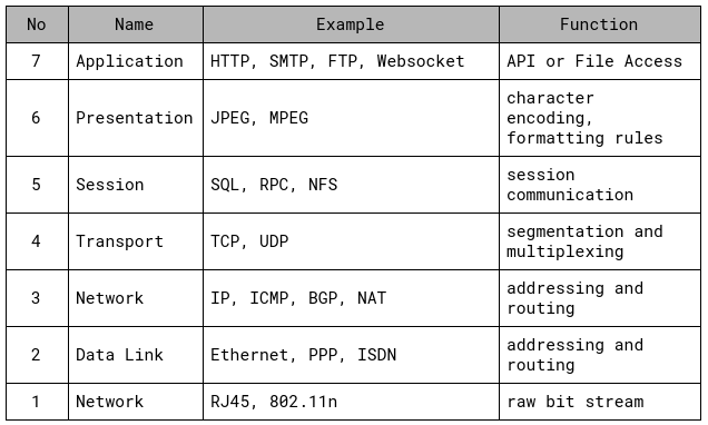
Layer 7: Application
The Application layer allows applications to communicate with the protocol stack. It ensures that sufficient resources are available to support the requested communication and is responsible for interfacing user applications, network services, or the operating system with the protocol stack.
The application is not located in this layer but rather the protocols and services required for it to work.
Layer 6: Presentation
Layer 6 imposes common or standardized structure and formatting rules onto the data from the application layer. It acts as an interface between applications and the network and therefore allows various applications to interact over a network. It does so by ensuring that the data formats are supported by both systems. Most data and file formats operate within this layer.
The formats include support for images, video, sound, digital rights, documents, emails, or text.
Layer 5: Session
The Session layer is establishing, maintaining, and terminating communication sessions between two computers. It manages dialogue discipline and control (simplex (one-way), half-duplex (two-way one-directional), full-duplex (two-way bi-directional)), establishes checkpoints for recovery, and can retransmit PDUs that have failed to the Transport layer.
Layer 4: Transport
This layer is responsible for managing the integrity of a connection and controlling the session. It accepts a PDU (Protocol Data Unit) from the Session layer and converts into segments. The Transport layer defines the rules of a session, how much data a segment can contain, how to verify the segment integrity, and how to determine if data has been lost. Rules are established through a handshake process (SYNC/ACK three-way handshake for TCP/IP).
Layer 4 establishes a logical connection between two devices and provides end-to-end transport services for data delivery. Mechanisms in this layer include sequencing, segmentation, error checking, controlling the data flow, error correction, multiplexing, and optimization.
Layer 3: Network
The Network layer is responsible for adding routing and addressing information to the data. It accepts the segments from the Transport layer and adds information to it to create a packet. The packer includes the source and destination IP address.
Layer 3 is responsible for providing routing and delivery information, but it’s not responsible for verifying guaranteed delivery. It also manages error detection and traffic control.
Routers are an example of network hardware devices functioning on this layer. Routers can determine the best logical path for transmission of packets based on speed, hops, preferences or priority. They use the destination IP address to guide the transmission of packets.
Non-IP Protocols are protocols that serve as an alternative to IP at the OSI Network layer. With the dominance of TCP/IP, non-IP protocols have become limited to special-purpose networks. Recognizable non-IP protocols are AppleTalk, NetBEUI or IPX
Layer 2: Data Link
The Data Link layer is formatting the packet from the Network layer into the proper format for transmission. The proper format is determined by the hardware and network technology. Ethernet remains a common Data Link layer technology in modern networks. Within the Data Link layer resides the protocol that converts the packet into a properly formated frame. Once the frame is formatted, it’s sent to the Physical layer for transmission.
Part of the processing performed on this layer includes adding the hardware source and destination address to the frame. This address is the Media Access Control (MAC) address. Network hardware functioning on layer 2 are switches and bridges. Switches support MAC-based traffic routing and receive a frame on one port and sent it out to another port based on the destination MAC address.
Layer 1: Physical
The Physical layer is responsible for receiving bits from the physical connection medium and converting them into a frame to be used by the Data Link layer. It also works the other way around by converting the frame into bits for transmission over the physical medium.
This layer contains the device drivers that tell the protocol how to employ the hardware for transmission and reception of bits. Located in this layer are electrical specifications, interface standards, and protocols. Layer 1 controls throughput rates, manages line noise and medium access, handles synchronization and also determines whether to use digital or analog signals.
Hardware devices that function at this layer are network interface cards (NIC), hubs or repeaters. These devices perform hardware-based signal operations. One example is a network hub that is sending a signal from one connection port to all other ports. A network repeater is amplifying a signal to support greater transmission distances.

Encapsulation and De-encapsulation
Protocols based on the OSI Model utilize a mechanism called encapsulation. It is the addition of a header, and possibly a footer, to the data received by each layer from the layer above before it is handed over to the layer below. As a message traverses the layers, it is enriched with additional data. The previous layers header and payload becomes the payload of the current layer.
Encapsulation occurs as data moves down through the OSI Model layers from Application to Physical. When data moves up through the layers from Physical to Application the action occurring is known as de-encapsulation.
The process is as follows:
1. The Application layer creates the message
2. The Application layer passes the message to the Presentation layer
3. The Presentation layer encapsulates the message by adding layer-specific information to it.
4. The process continues as the original message travels down the layers. Each layer adds additional information to the message
5. The message reaches the Physical layer and is converted into electrical impulses that represent bits and is transmitted over the physical connection
6. The receiving computer captures the bits from the physical medium and re-creates the message in the Physical layer
7. The Physical layer converts the message from bits into a Data Link frame and sends the message up to the Data Link layer
8. The Data Link layer strips the layer-specific information from the message and sends it up to the Network layer
9. The process of de-encapsulation is performed on each layer until the message reaches the Application layer
10. On the Application layer, the data is extracted from the message and is sent to the intended software recipient
The information added and removed by each layer contains instructions, checksums, and can only be understood by the peer layer that added or created the information. This creates the logical channel that enables the peer layer on different computers to communicate.
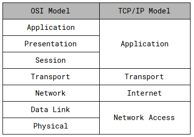
TCP/IP and OSI comparison
The TCP/IP or DARPA Model was developed before the OSI Model. The designers of the OSI Reference Model made sure that both fit together because TCP/IP was already an established deployment in networking.
TCP/IP is the most widely used protocol stack with dozens of individual protocols. It is platform-independent and based on open standards and can be found in every available modern operating system. The drawbacks of TCP/IP are its significant consumption of resources and the lack of security by design.
Conclusion
The theory behind the OSI model is abstract at first but it serves as a model to understand and compare protocols. It also helps vendors and developers to create digital communication products that interoperate. Lastly, the structure of the OSI model helps to frame discussions of protocols and contrast various technologies.